All area diagrams · Exact configuration
LONGER B1 40W configuration reference
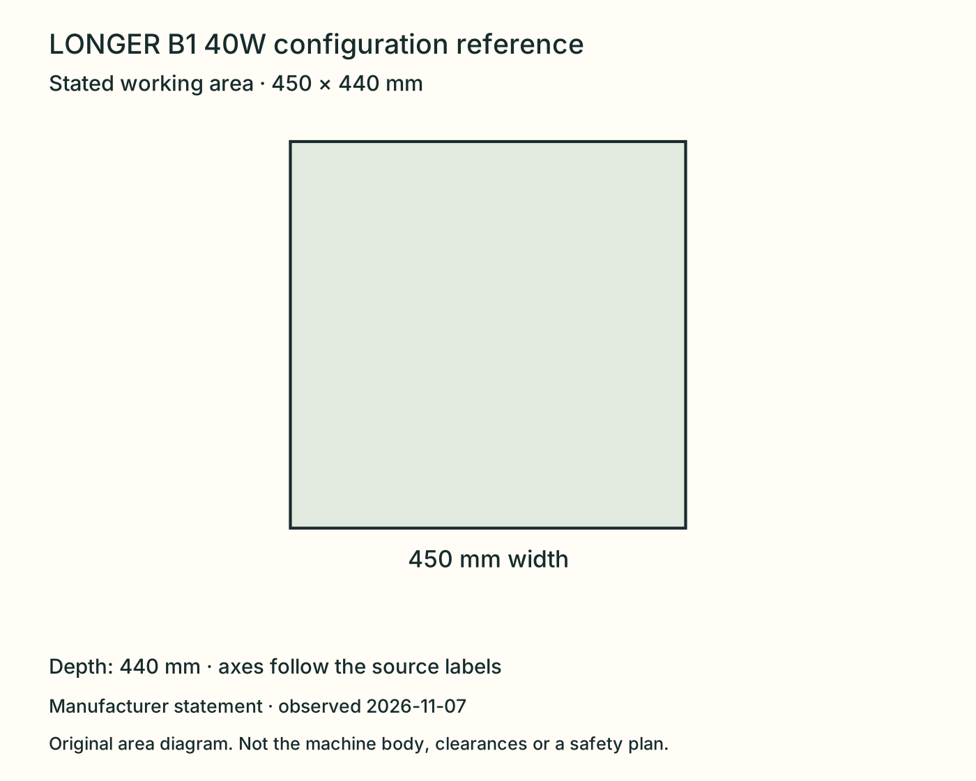
Original working-area diagram. The rectangle is not the machine footprint, a clearance drawing or a safety plan.
Read the source rectangle, one axis at a time
- Solid source rectangle
- 450 × 440 mm stated work area. Source · 2026-11-07
- Dashed example rectangle
- 420 × 400 mm; original illustrative planar outline, not a tested finished part.
- This bounded comparison
- The unrotated example outline is contained on both source axes. No rotation is applied; clamping, fixtures, material/process and quality remain separate.
Original source-based and illustrative-part geometry. The shapes share one scale within this figure, not a ruler scale across separate detail pages. This is not a machine photograph, measured usable bed, approved cut path, operating recipe or installation plan.
Three distinct geometry questions
Working area
450 × 440 mm, with the source’s stated axes.
Not a cabinet, stand or loading envelope.
External machine body
External body dimensions unresolved. The work-area rectangle cannot supply them; a drawn enclosure would be invented geometry.
Body and working-area orientations are not reconciled or nested.
Access, extraction and operation
Exact reservations unresolved. Lid/door travel, loading, cables, extraction route, service, person and room constraints need separate documentation.
No arbitrary clearance dimension is drawn.
Original boundary legend: only admitted dimensions are numeric. Unknown geometry stays unknown. Working area is not usable clamped area; body dimensions do not establish installation, exhaust or safe operation.
Open the original prepared vector and source reference
Dimensions are manufacturer statements, not independently measured. Confirm usable clearance, clamping, access, extraction and the exact current installation documentation separately.